Preparation and materials:
Cut 4 RED wires @ 5" each and strip off both ends about 3/4"
Cut 3 BLACK wires @ 5 " each and strip off both ends about 3/4"

3 LEDs (2 Blue, 1 Green)
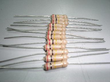
3 Resistors
1 Switch (on/off)

1 Battery pack (holds 3 AA)

Soldering tool and solder
STEPS:
1. Solder 1 resistor to the positive end (longer end) per LED.
2. Solder 1 RED wire to the end of each resistor.
3. Hand twist 3 RED wires together along with the 4th RED wire.
4. Solder the end of the 4th RED wire to 1st prong of switch.
5. Solder RED wire from battery pack to 2nd prong of switch.
6. Solder 1 BLACK wire to the negative end (shorter end) per LED.
7. Hand twist 3 BLACK wires together.
8. Solder BLACK wire from battery pack to the 3 BLACK wires and solder together.
![[Diagram+Model+(1).jpg]](https://blogger.googleusercontent.com/img/b/R29vZ2xl/AVvXsEij_qJxeW64wuZn5S6wpsA8tHw1Z0nG_nSZWfr3UCFMi-bjOFxHu8l4cz7TRCNAVISrYWrona0ANYFG6By7W51r9avz_wXhoWGbkjUdYdZWwfuqB9w58HIzQJIJ6W2__8ST3I9oBtkgLbo/s1600/Diagram+Model+(1).jpg)
hello... hapi blogging... have a nice day! just visiting here....
ReplyDelete